

This content is provided for informational purposes only and does not constitute professional engineering advice. Consult a certified expert before implementing any lightning protection system.
Every industrial facility carries a measurable exposure to lightning — and that exposure can be quantified, mapped, and addressed through a rigorous design process. Whether the site houses chemical reactors, pharmaceutical cleanrooms, or data center infrastructure, the principles governing a reliable lightning protection system follow the same structured logic: assess the actual risk, select the appropriate protection level, then size each component accordingly. This guide breaks down that process, from the normative framework that governs it to the operational decisions that determine whether a system genuinely performs under storm conditions.
Your three starting points for industrial lightning protection:
- Risk assessment must precede any equipment selection — the IEC 62858 density map is the baseline input, not an optional reference.
- NF EN 62305 defines four protection levels (LPL I to IV); choosing the wrong one means your system is either insufficient or over-engineered for your actual exposure.
- Regulatory compliance for ICPE-classified sites in France is not optional: the decree of 19 July 2011 mandates documented lightning risk analysis and periodic verification.
The gap between a system that meets a paperwork requirement and one that actually protects operations comes down to how thoroughly the initial risk analysis was conducted. Many industrial sites still operate with lightning protection designed against outdated density data or generic protection levels that do not reflect site-specific factors — a situation that regulators and insurers are increasingly scrutinizing.
Before reaching the sizing questions, it is worth understanding the normative architecture that structures every legitimate design decision in this field.
The normative framework: IEC 62858, IEC 62793, and NF EN 62305
Navigating industrial lightning protection requires a clear understanding of the regulatory environment. Three major international and national references dictate the design, implementation, and monitoring of these systems, ensuring they meet the highest safety requirements.
What each standard actually governs
Three normative references structure industrial lightning protection design, and they are not interchangeable. Each operates at a distinct layer of the design process. IEC 62858 deals exclusively with the measurement and mapping of lightning ground flash density — it is the statistical foundation that feeds every subsequent calculation. IEC 62793 addresses the design and performance of thunderstorm warning systems, covering detection range, alert thresholds, and the criteria for resuming outdoor activities after a storm event. The NF EN 62305 standard series, published in its consolidated version by AFNOR in 2023, is the overarching design code: it integrates risk assessment methodology, defines the four Lightning Protection Levels (LPL I through IV), and specifies the technical requirements for both external and internal protection systems.
The distinction matters operationally. An engineer relying on IEC 62858 data without applying the NF EN 62305 risk assessment framework is working with accurate density figures but no method to translate them into a protection decision. Conversely, applying NF EN 62305 with outdated or spatially averaged density data produces a protection level that may be systematically miscalibrated for the actual site exposure.
How the standards interact in a real design workflow
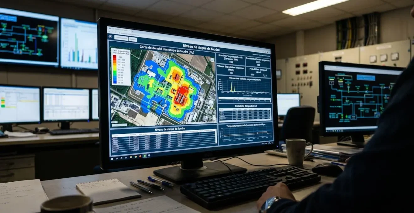
In practice, the design sequence runs from measurement to assessment to specification. IEC 62858 density data — sourced from a certified lightning location network — feeds the risk calculation defined in NF EN 62305 Part 2. That calculation produces a risk value R, which is then compared against a tolerable risk threshold RT. The outcome determines which LPL applies, and that LPL in turn governs every sizing parameter downstream: conductor cross-sections, mesh widths, surge protective device (SPD) ratings, and separation distances between the lightning protection system (LPS) and structural elements. To ensure a reliable design, it is critical to move beyond regional averages. Specialized services providing lightning protection for industrial plants now deliver high-resolution density data as required by IEC 62858. By integrating historical strike records from certified networks, engineers can populate the NF EN 62305 risk calculation with site-specific inputs. This level of precision is the only way to justify the chosen Lightning Protection Level (LPL) to regulators and insurers alike.
Standards in context: NF EN 62305 is structured in four parts — Part 1 (general principles), Part 2 (risk management), Part 3 (physical damage to structures and life hazard), and Part 4 (electrical and electronic systems within structures). A complete industrial LPS design requires engaging with all four parts, not just Part 3, which covers the visible hardware.
The interaction between these three normative instruments is sequential, not parallel. Skipping or approximating any layer introduces cumulative error into the final design. This is the structural reason why lightning protection design for industrial sites cannot be reduced to selecting an air termination rod from a catalog and following a generic installation guide.
Industrial lightning risk assessment: methodology and inputs
The efficiency of a Lightning Protection System (LPS) is directly proportional to the accuracy of the data used during the calculation phase. A generic assessment often leads to costly failures or unnecessary over-engineering.
Quantifying ground flash density (Ng) and its implications
The ground flash density parameter Ng — expressed as the number of lightning flashes per square kilometer per year — is the single most consequential input in the NF EN 62305 risk calculation. A variation of even 0.5 flashes/km²/year can shift the calculated risk value across the LPL threshold, changing the entire protection architecture. According to the official lightning density mapping, covering the period 2015-2024, Ng values across metropolitan France vary from below 0.5 in coastal Atlantic zones to above 4.0 in the Alpine foothills and parts of the Massif Central — a factor-of-eight range across the same country.
0.5 – 4.0+ fl/km²/yr
Range of lightning ground flash density values across metropolitan France, from low-exposure coastal zones to high-exposure Alpine areas (Météorage, 2015-2024 reference map)
Using a regional average Ng value rather than site-specific data is one of the most persistent errors in industrial LPS design. The practice survives because regional averages were historically the only data available at the resolution needed for site-level calculations. High-resolution location network data has made this workaround unnecessary — and in ICPE-regulated environments, regulators increasingly expect documented justification for the Ng value used in the risk file.
Site-specific factors that shift the protection level
Ng is not the only variable. The NF EN 62305 Part 2 risk formula incorporates several site-specific correction factors that can raise or lower the calculated risk independently of the density figure. Structure height directly affects the effective collection area; a 40-meter storage tank collects significantly more lightning exposure than the Ng figure alone would suggest for a low-profile building at the same coordinates. The nature of the content — flammable liquids, explosive atmospheres, critical electronic systems — determines the tolerable risk threshold RT, which for ATEX zones or facilities with life-safety implications is set at a far lower level than for general industrial structures.
Operational scenario: petrochemical loading bay
Consider a petrochemical site where 200 operators must be moved to shelter during storm events, with sequential shutdown of loading operations to prevent ignition risk. The challenge in this configuration is not just selecting the right LPL — it is coordinating the alert threshold from the IEC 62793-compliant warning system with the operational lead time required to halt tanker loading and move personnel. A system calibrated to alert at 10 km storm proximity gives roughly 10-15 minutes of lead time. If the loading bay shutdown sequence requires 20 minutes, the alert threshold needs to be extended to 20-25 km — which in turn increases the number of unnecessary production interruptions. This trade-off between safety margin and operational availability must be explicitly modeled during the risk assessment phase, not resolved ad hoc during a storm event.
The guide d’application from the NSA Groupe Ampère laboratory provides detailed criteria for applying the correction factors within the NF EN 62305 framework, including worked examples for sites with mixed-use zones and structures of varying heights. It is one of the few publicly available French-language academic references that goes beyond restating the normative text to show how the calculation is actually applied on complex industrial footprints.
Designing the protection system: architecture and component sizing
External protection: air termination and down conductors
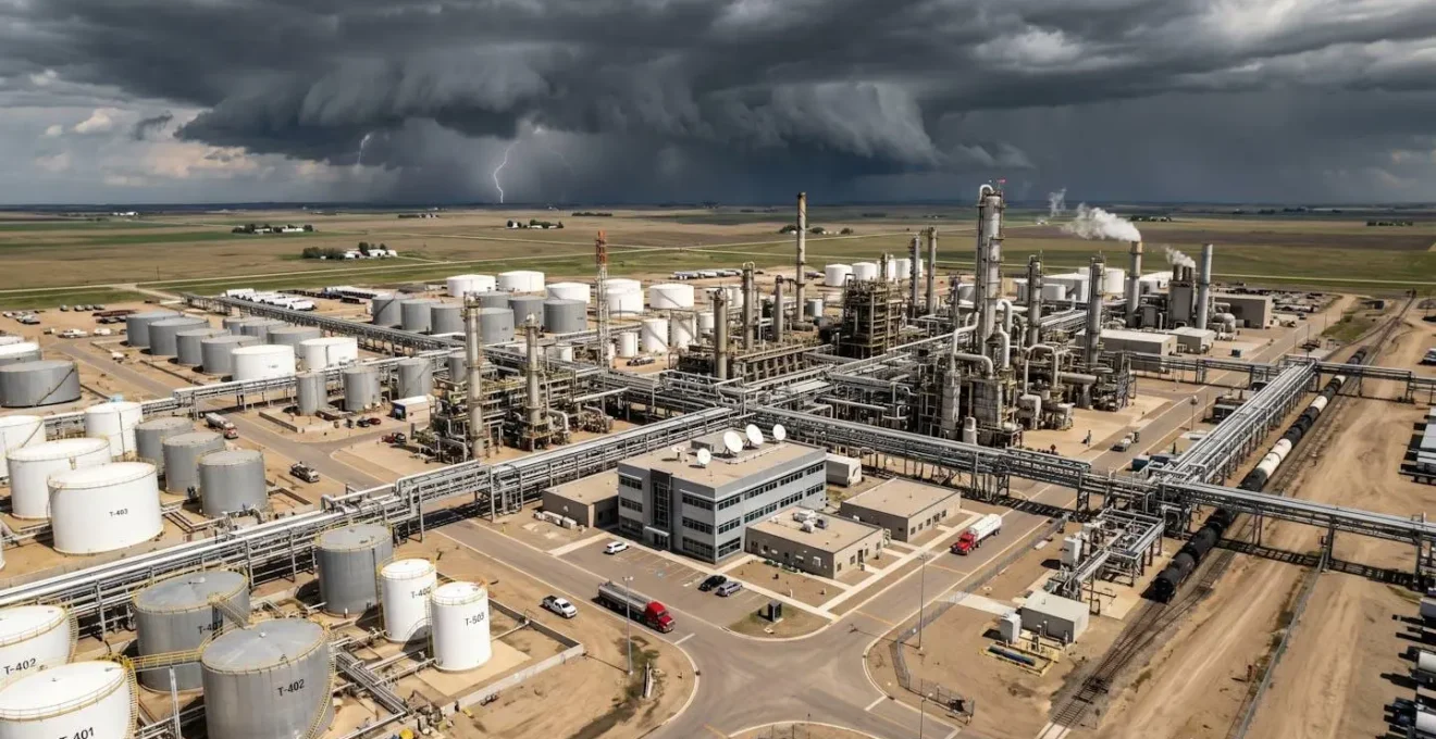
Once the LPL has been determined, the external protection system — air termination network, down conductors, and earth termination system — is sized according to the rolling sphere, mesh, or protective angle methods defined in NF EN 62305 Part 3. The rolling sphere radius varies by LPL: 20 meters for LPL I (highest protection), 30 meters for LPL II, 45 meters for LPL III, and 60 meters for LPL IV. This parameter directly controls how many air termination points are required and where they must be positioned relative to the protected structure.
For large industrial structures — elevated tanks, process columns, conveyor gantries — the mesh method is often more practical than the rolling sphere approach because it can be applied systematically across extended horizontal surfaces. The trade-off is that mesh coverage requires a greater number of conductors and connection points, which increases installation cost and maintenance complexity. The protective angle method is generally reserved for isolated structures with simple geometry, such as standalone transformer substations or guard posts at site perimeters.
-
If the structure has a simple, isolated geometry (single building, standalone silo):
The protective angle method offers the fastest path to a compliant design. Verify that height and LPL combination remains within the method’s validity limits defined in NF EN 62305 Part 3.
-
If the structure has a large flat roof or extended horizontal surface:
The mesh method is the most reliable approach. Mesh width is 5×5 m for LPL I, up to 20×20 m for LPL IV. A BIM-compatible layout tool significantly reduces dimensioning errors on complex footprints.
-
If the structure includes elevated process equipment or tanks with floating roofs:
The rolling sphere method is the most rigorous option. Apply a sphere radius corresponding to the site LPL and verify all exposed points are within the protected volume. Coordination with ATEX zone mapping is mandatory.
-
If the site combines all of the above:
A hybrid approach is both permitted and standard practice. Document the method applied to each structural zone separately in the LPS study file to facilitate inspection by the approved control body.
Down conductor routing on industrial sites requires additional attention beyond what residential or commercial applications demand. Process pipework, cable trays, and metallic structural elements create complex electromagnetic environments where induced voltages can cause secondary damage even when the direct strike is intercepted. Separation distances between the LPS conductors and internal metallic systems must be calculated for each LPL using the formula in NF EN 62305 Part 3, and the results documented before installation begins.
Internal protection: surge protection and equipotential bonding
The internal lightning protection system — governed by NF EN 62305 Part 4 — addresses the secondary effects of a lightning event: electromagnetic impulse, conducted surges on power and data lines, and step-and-touch voltage gradients within the facility. For industrial sites with distributed control systems, programmable logic controllers, or safety instrumented systems, Part 4 is frequently the most technically demanding component of the full LPS design.
Equipotential bonding is the foundational measure. All conductive systems entering the protected volume — power supply cables, signal cables, metallic pipes, data network cables — must be connected to a common equipotential bonding bar (EBB) at the point of entry. Surge protective devices (SPDs) are then selected based on the lightning protection zone (LPZ) boundary they protect and the maximum impulse current they must handle for the applicable LPL. The LPZ concept divides the facility into zones of decreasing electromagnetic severity — from LPZ 0 (direct exposure) to LPZ 2 and beyond (protected interior spaces) — and each zone boundary requires SPDs rated to handle the current differential between adjacent zones.
Operational scenario: data center with uninterruptible critical load
A data center hosting critical infrastructure requires both physical protection against direct strikes and uninterrupted service continuity during nearby lightning events. The LPZ design for this facility must ensure that SPDs at the LPZ 0/1 boundary (typically at the main distribution board) limit the residual voltage to a level safe for equipment at the LPZ 1/2 boundary (server room distribution). If the coordination between Type 1, Type 2, and Type 3 SPDs is not verified against the specific equipment immunity levels, a lightning event 500 meters away can generate a conducted surge that damages servers without triggering any external protection — because the external LPS did exactly what it was supposed to do, and the internal system was simply not coordinated correctly.
The SPD coordination study — verifying that the voltage protection level (Up) of each SPD is lower than the withstand voltage of downstream equipment — is often underestimated in its complexity. Equipment manufacturers specify impulse withstand categories (I to IV per IEC 60664-1), and the SPD chain must be designed to ensure that residual voltages remain below those thresholds at each distribution level. For facilities running safety instrumented systems with SIL-rated components, this coordination is a formal engineering deliverable, not a field adjustment.
Operational integration: alerts, production continuity, and compliance
A complete lightning protection strategy for an industrial site extends beyond the physical LPS. The IEC 62793 standard addresses the operational layer: thunderstorm warning systems that give site operators actionable advance notice of storm proximity, enabling controlled shutdown of hazardous outdoor activities before lightning exposure begins. The standard specifies minimum detection range, alert lead times, and the criteria for issuing an all-clear signal — the last point being operationally critical, because resuming activities too early after a storm accounts for a significant share of lightning-related incidents at industrial sites.
Integrating a compliant warning system with site operations requires mapping the alert thresholds against the actual shutdown and evacuation times for each operational zone. A loading bay with a 20-minute shutdown sequence, a crane operation requiring 15 minutes to secure, and an outdoor maintenance crew needing 8 minutes to reach shelter all require different alert distances — and a single site-wide threshold will inevitably be either too conservative for some operations or insufficient for others. The standard practice is to establish zone-specific response protocols tied to a tiered alert structure: pre-alert (storm within defined outer radius), operational alert (storm within action threshold), and all-clear (minimum clear period elapsed post-last-strike).
Regulatory compliance for French ICPE-classified sites is governed by the decree of 19 July 2011, which mandates documented lightning risk analysis, periodic verification by an approved control body, and maintenance of the LPS in conformity with the applicable standards. The risk analysis must be updated whenever significant modifications are made to the site — new structures, changes in process content, or modifications to electrical infrastructure that alter the LPZ configuration. Treating the risk analysis as a one-time deliverable rather than a living document is the compliance failure pattern most frequently cited during administrative inspections.
Verification intervals depend on the LPL assigned to the site: LPL I and II installations require verification by a competent body every year, while LPL III and IV systems are typically verified every two years in the absence of incidents. Any direct strike recorded on the site triggers an immediate verification requirement regardless of the scheduled interval — because a strike at or near the design current threshold for the applicable LPL may have caused degradation to bonding connections, SPD modules, or earth electrode resistance that is not visible without measurement.
What is the difference between LPL I and LPL IV, and how is the correct level determined?
LPL (Lightning Protection Level) I offers the highest degree of physical protection, designed to intercept lightning currents up to 200 kA, while LPL IV is calibrated for 100 kA. The correct level is determined through the NF EN 62305 Part 2 risk calculation, which compares the site’s calculated risk R against the tolerable risk threshold RT. For ATEX zones, sites with life-safety implications, or critical infrastructure, the RT threshold is set significantly lower, which typically drives the calculation toward LPL I or II regardless of the local Ng value.
Is a thunderstorm warning system (IEC 62793) a substitute for a physical lightning protection system?
No. A warning system addresses the operational risk to personnel and time-sensitive processes — it provides advance notice to enable controlled shutdowns and evacuation. It does not replace the physical external LPS (air termination, down conductors, earth termination) or the internal SPD and bonding infrastructure. Both layers are required for a complete industrial lightning protection strategy: one protects the structure and systems from the effects of a direct strike; the other protects people and operations from the consequences of nearby storm activity.
How frequently must an industrial LPS be verified under French ICPE regulations?
The 19 July 2011 decree requires periodic verification by an approved control body, with intervals that depend on the assigned LPL. Sites with LPL I or II must plan for annual verification. A direct strike to the installation triggers an immediate verification requirement outside the regular schedule. The risk analysis itself must be updated whenever the site undergoes significant modifications to structure, process content, or electrical infrastructure.
Can a site use a single alert threshold for all outdoor operations?
A single threshold is technically simpler to manage but operationally suboptimal. Activities with longer shutdown sequences (crane operations, tanker loading, hot work) require greater advance warning than activities that can be halted immediately. The recommended approach, consistent with IEC 62793 implementation guidance, is to define zone-specific alert distances matched to the actual response time of each operational activity, then configure the warning system to generate tiered alerts that trigger the appropriate zone-level protocols.
The techniques de protection électrique industrielle deployed across a site work as a coordinated system — the physical LPS intercepts direct strikes, the SPD chain absorbs conducted surges, equipotential bonding eliminates voltage differentials, and the warning system provides the operational lead time to protect personnel. When any one layer is absent or miscalibrated, the others cannot fully compensate. Understanding how these layers interact is what separates a lightning protection design that satisfies an inspection checklist from one that continues to perform reliably after the first major storm event the site experiences. For further context on the broader landscape of industrial electrical protection techniques, the interaction between LPS design and the electrical infrastructure of modern energy systems adds additional dimensions worth examining.
Your verification priorities before commissioning
The distance between a completed LPS design and a fully compliant, operationally integrated installation is covered by a structured commissioning and documentation process. The items below translate the normative requirements into the concrete verification actions that an HSE manager or site engineer should be able to confirm before the system is signed off.
-
Confirm that the Ng value used in the risk calculation comes from a certified, site-specific source (IEC 62858 compliant), not a regional average — and that it is documented in the risk study file.
-
Verify that the LPL assigned to each structural zone matches the NF EN 62305 Part 2 risk calculation output, with correction factors for structure height and content type explicitly recorded.
-
Check that SPD coordination has been documented across all LPZ boundaries, with the residual voltage protection level (Up) verified against the impulse withstand category of downstream equipment.
-
Ensure that the IEC 62793 warning system alert thresholds are mapped to written operational response protocols by zone, including explicit all-clear criteria tied to last-strike detection timestamps.
-
Schedule the first verification by an approved control body and confirm that the ICPE regulatory file includes the complete risk analysis, LPS technical study, and verification schedule — ready for inspection.
Lightning protection work that progresses from a rigorous site-specific risk assessment to a correctly sized, well-documented installation is also well-positioned for another outcome: a defensible compliance file that holds up under regulatory scrutiny. The two objectives — protecting the site and satisfying the regulator — are built from exactly the same inputs. A guide on the deployment of renewable energy illustrates how energy infrastructure decisions at the facility level increasingly intersect with protection system design — particularly for sites combining solar generation, battery storage, and conventional industrial loads.
Scope of this guide: The methodology described here reflects the structure of established normative frameworks as of the referenced publication dates. Standards are subject to revision; verify that the edition in force at the time of your design project has been consulted. Each industrial site presents specific conditions — structure geometry, process hazard classification, soil resistivity, electromagnetic environment — that require site-specific analysis by a certified lightning protection specialist or approved control body. This guide does not substitute for that analysis.